


AkzoNobel Q1 core profit beats analysts’ predictions
Dutch paints and coatings giant says it expects a “strong” 2024

Industry Insights

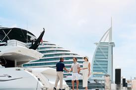
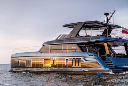
Seth Hynes | president, HH Catamarans
Last November HH Catamarans picked up the coveted Breakthrough Launch of the Year award for its new HH44 at the 2023 Boat Builder Awards organised jointly by IBI and METSTRADE and held in association with Raymarine. We talked to company president Seth Hynes about the impact of the award and ...

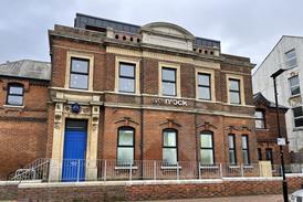
Profile | Spinlock - Delivering the goods
Diversifying its portfolio whilst working quicker and smarter has enabled the UK accessories manufacturer to stay one stap ahead of the pack

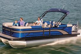
Insight | Sustainability: Here and now
With growing consumer interest in environmental sustainability, boatbuilders look to future technologies as a means of solidifying their engagement with eco-conscious buyers. But what can the industry do right now to be more sustainable? Quite a bit, it turns out, with a range of green options already available to boatbuilders
Featured Content
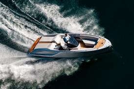
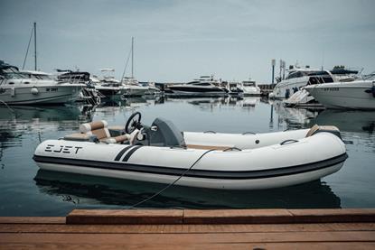
ZeroJet enters into supply partnership with Highfield Boats
French-Chinese RIB manufacturer to offer New Zealand-made ZeroJet electric jet propulsion system with 2023 product line
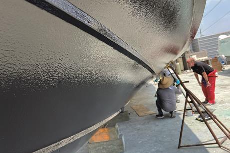
Two decades of high-end yacht coating development
Alexseal Yacht Coatings celebrates its 20th anniversary by reflecting on its origins as a part of long-established coating solutions manufacturer Mankiewicz, its mission today and intentions tomorrow
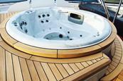
Wolz Nautic Italy adopts additive manufacturing for faster delivery of custom boat designs
Wolz Nautic Italy, a worldwide leader in teak deck design, production and fitting, has purchased a Massivit 5000 industrial 3D printer to increase its capabilities when offering complex solutions for manufacturing custom elements while improving accuracy and saving on time and resources.
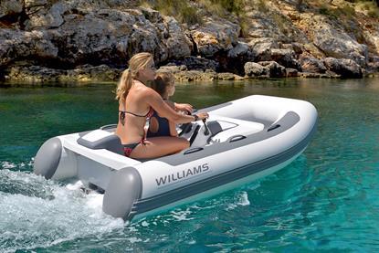
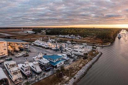
MarineMax completes Williams Tenders USA acquisition ahead of schedule
Acquisition of tender business expected to be accretive to earnings in first full year of operations
Electric motor innovator Molabo sold
Manufacturer to tap into new owner’s production and scaling know-how


![940197ed-1a36-a4bc-7959-0ef97d6ad381[1]](https://d1ajyvl96t5n4x.cloudfront.net/Pictures/415x277/5/4/8/42548_940197ed1a36a4bc79590ef97d6ad3811_619627.jpg)
 LinkedIn
 X / Twitter
 Facebook
 Email us